Linkage Design Overview

“Linkage Design” is a computer program used to speed and improve the setup of radio controlled airplane control systems. The program accurately simulates the geometry of the servo-to-surface linkage system for several different servo arrangements. The program enables the rapid manipulation of the system geometry so that a rapid “cut-and-try” process leads to desired control surface deflections. In addition to providing rigorously accurate deflections, the program provides approximate servo and pushrod loads so that these may be sized.
Four different linkage arrangements are supported. Three use the standard servo arm - pushrod - control horn linkage. The fourth uses a rotary linkage that drives the surface via a bent torque rod.
The program runs in Microsoft Excel, so the modeler can easily modify the program to suit his needs or explore the guts of the program to see what makes it tick. The program runs on any computer with Microsoft Excel 97 or later.
Key Features
• Immediate design feedback from 2-D or 3-D drawings of the linkage system
• Four different servo installation types supported in a consistent format
• Precise calculation of control surface deflection
• Approximate calculation of servo torque plus calculation of linkage rigidity for the rotary configuration
• Implementation in Microsoft Excel for ease of modification
-
•English or metric inputs and outputs
What You Get
• Linkage Design is a single spreadsheet with four separate programs located on four pages.
• Linkage Design comes with 14 pages of illustrated instructions in the Adobe Acrobat (.pdf) format. A software reader for this format is available free from Adobe.
• The spreadsheet and instructions are delivered in electronic form - either on a mailed CD ROM disk or as an email attachment of about 900 kilobyte size.
How to Use “Linkage Design”
The program can be used in the design process or after the model is built and the servos are installed.
In the design process, the designer can use the program to help locate the servos, select servos and optimize the linkage design. During the final phase of setting up the linkage for a nearly finished airplane, the modeler can optimize the geometry and provide a check on the servo and pushrod loads. The process is about the same either way.
The following is extracted from the instructions that come with the program. More detail is provided in the other pages listed at the bottom of this page.
1. Load and open the program
“Linkage Design” is a Microsoft Excel spreadsheet. It is delivered ready-to-go. Put the program on your hard disk, make a spare copy and put that someplace for safekeeping. It is possible to make a mistake when using the program and damage it. If you do make a mistake, close the program without saving and start over. In the event that you accidentally save a damaged program it is good to have a backup copy available.
Open the program in Microsoft Excel. Note that there are four separate pages that can be reached by clicking on the four tabs at the bottom left of the page as shown to the right.
2. Decide on servo installation type
Four servo installation types are supported. These are:
Long Pushrod – This type is used when the servo is a long way from the control surface. An example of this type is an elevator or rudder servo mounted well forward in the fuselage at a long distance from the control surface. For this type, the geometry calculation does not take into account variations in pushrod angle as the servo arm and control horn move. The orientation of the servo is irrelevant - the servo axis may be parallel to the hinge axis, perpendicular or any angle in-between.
Short Pushrod – Use this type for servos that are mounted a short distance from the control surface and where the servo arm axis is parallel to the surface hinge line. This type of installation is common in sailplanes where the servo is entirely buried in the wing and only the tip of the servo arm sticks out of the wing. Another possibility is elevator servos that are mounted directly to the side of the fuselage so that the upper portion of the servo is exposed and the servo arm axis is parallel to the hinge axis.
Perpendicular Axis Pushrod – Use this type for servos that are mounted a short distance from the control surface where the servo arm axis is perpendicular to the control surface hinge line. This type of installation is often seen in large power models where the servo is mounted upright in a wing or tail surface so that the upper portion of the servo is exposed. This type would also apply for a rudder servo mounted upright in the side of the aft fuselage.
Rotary – This type is quite different from the typical servo installation. It mounts the entire servo and linkage within the wing surface and can provide a modest but significant drag reduction and reduce airframe noise. The rotary actuation mechanism uses a shaft that extends from the servo axis through the hinge line. At the hinge line, the shaft is bent so that it moves up and down with servo rotation. The shaft is captured between two parallel plates mounted within the surface so that this vertical motion is translated to the control surface. Motion of the system is governed by the bend in the drive shaft and the angle of the servo axis relative to the hinge line. High quality hardware for this linkage is marketed by Harley Michaelis as the Rotary Driver System (RDS) system.
3. Pick the correct page of the spreadsheet
Use the four tabs at the bottom left of the spreadsheet to pick the appropriate page to use for the linkage type you are designing. It is possible that your specific linkage is not exactly the same as any of the four. If this is the case, pick the one that is closest. Perfection is usually not required, and small adjustments can be made in the actual final setup of the airplane.
4. Enter preliminary geometric data
Start the design process by entering in starting point data for your setup. This is done in the “Geometry Input” and “Hinge Moment Input” sections.
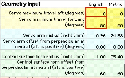
Input is made by using the little up/down arrows. Just click on the up or down arrow next to each value to increase or decrease the value. Rapid changes can be made by holding the arrow down instead of clicking. DO NOT type a value into the block directly – this will damage the program! This can be done only in the few input blocks outlined in red. This limitation is an unavoidable result of Excel’s internal design.
The “short pushrod” and “perpendicular axis pushrod” types assume that the servo linkage protrudes from the bottom of the wing surface. It is not possible in the program to flip it to the top side. If you need a top-mounted design you must mentally flip the picture, and all “up” deflections to “down” and vice-versa.
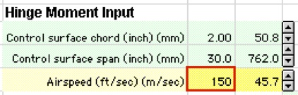
The value of the control surface chord should be close to the average chord. Airspeed is used to calculate the load on the servo. Airspeed is typically be the maximum airspeed, but it can be varied to find the maximum speed a given servo can achieve a certain surface deflection, for instance.
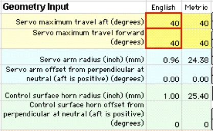
The program is set up so that at zero servo deflection (not zero servo arm deflection) the control surface is faired (zero deflection). This means that the control surface will be centered when the stick is centered. For the rudder, elevator and ailerons set the servo throw to equal and nearly maximum magnitude both up and down as shown in the figures to the right. Use the horn geometry to achieve the correct throw and differential, if desired. Differential refers to asymmetrical deflection in the up and down direction – this is common for ailerons in order to avoid adverse yaw. The goal here is to use the full servo travel. It may be possible with some computer-aided transmitters to use full servo travel even if up and down servo travel is not the same. This is a good solution also.
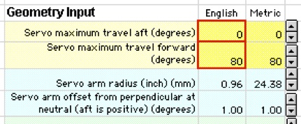
For flaps, set the servo throws so that there is zero travel in the up direction and maximum travel in the down direction as shown in the figures to the right. This maximum will be the sum of the servo throws from the center position. For instance, if the servo is capable of 40° throw each way from center, set the flap servo throws to 0° up and 80° down. This will help to provide the least load on the servo.
5. Play with the design a bit
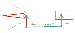
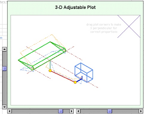
As you change values you will notice that the drawing of the linkage system changes too. This feature gives design insight as to what is happening and is intended to simulate the typical setup process on a real model – only in this case it is much faster.
Note that three control surfaces and linkages are shown. This represents a variable “current value” plus the maximum and minimum limit values. A slider bar at the right, lower side of the drawing controls the current value and moves the servo. This can be moved in small increments by clicking on the arrows at either end of the slider. It can be moved in bigger increments by clicking in the gray area on either side of the slider.
The view angle of the 3-D drawings can be varied. This is done with the slider bars near the lower left-hand corner of the drawing. A full plan view or full side view can be reached.
The maximum deflections of the control surface are controlled by the geometry inputs.
Note the “Maximum/Minimum Outputs” and “Current Values” output blocks. These are used as feedback in the design process along with the drawing of the system.
For more information, see the other Linkage Design pages listed below.
6. Refine the design
In general, the object of the design game is to achieve target control surface deflections (up, down and center) with the minimum servo load. Other goals of the design are to pick an appropriate servo and pushrod capacity. Alternatively, if the servo and pushrod are already selected, it can be a goal of the design process to determine the maximum speed at which the model can fly with certain control surface deflections.
Several tools are provided to help in the refinement process. The drawing is the key tool because of the insight it provides into the mechanism. The two output blocks are useful also in terms of hard numbers. Several additional plots are provided that give additional insight into the design. These plots are located directly below the main upper portion of each sheet.
“Control Surface Position v/s Servo Arm Position” plots two things relative to the servo arm position. It plots the control surface position and it plots the surface to servo deflection ratio. This is sort of the “gear ratio” between the surface and the servo. Larger values mean that the surface moves more relative to the servo and that the servo load is increased. Ideally, this curve would be shaped concave down so that the servo has better leverage at the ends of travel where the air loads on the surface are the greatest. This is not always so easy to achieve.
“Approximate Servo Torque v/s Control Surface Position” indicates the servo torque over the range of servo motion. It is the product of the air loads on the control surface and the surface-to-servo deflection ratio. This plot can be used to pick off maximum servo deflections for a limited servo torque capacity. Maximum, minimum and current servo torque values are also reported in the numerical output blocks.
“Pushrod Force v/s Control Surface Position” indicates the pushrod load. This can be used to design or pre-test the pushrod to make sure that it has sufficient strength and buckling resistance. Pushrod loads can be reduced by proportionally lengthening the servo arm and control horn. Maximum, minimum and current pushrod force is also reported in the numerical output blocks.
Check the other Linkage Design pages for more detail and information. In particular, "Fine Points" picks up the discussion where this page leaves off.
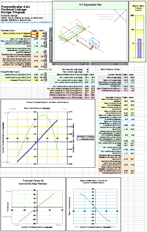
Linkage Design overview - This image shows the arrangement of one of the four spreadsheets. This same arrangement is used for all four linkage types. Key elements are the input blocks, drawing, output blocks and plots.

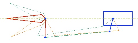
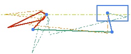
Long Pushrod geometry may be used for forward-mounted rudder or elevator servos. In this arrangement, the servo horn does not have to be coplanar with the control surface horn - the orientation does not matter.
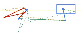
Short Pushrod geometry is used where servos are close to the control surface and the variation in pushrod angle is significant. The servo arm must be approximately coplanar with the control surface horn (perpendicular to the control surface hinge axis).
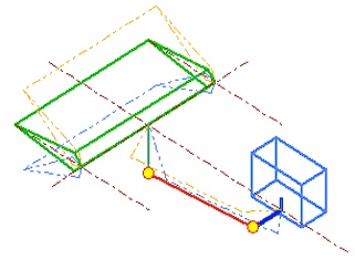
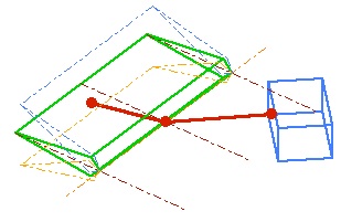
Perpendicular Axis Pushrod is used for servos mounted directly in a wing or tail surface where the servo axis and hinge axis are approximately perpendicular. This 3-D plot can be viewed from any angle.
Rotary is used for rotary servo drives. In this system a short, bent torque rod actuates the control surface via a precise internal slot in the surface. The chief benefit of this system is reduced drag and noise due to the absence of external linkage. This 3-D plot can also be viewed from any angle.